How to Solder AWG 32 Wire to a Rigid-flex PCB
- TOP
- Pulse Heat (Hot Bar Reflow) Soldering
- Applications of Pulse Heat (Hot Bar Reflow) Soldering
- How to Solder AWG 32 Wire to a Rigid-flex PCB
As generative AI becomes widespread, data centers require higher processing speed. Higher speed depends on faster communication between devices.
DAC cables require performance in the 800G to 1.6T range.
To increase communication speed while using standard-size boards and connectors, more cables are needed.
Server racks have limited space. Therefore, thinner DAC cables are required to increase cable count.
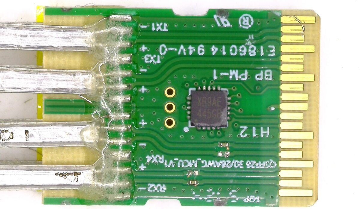
Soldering very thin AWG32 wires to the rigid board of the connector requires careful attention.
Challenges in soldering AWG32 Wire to a Rigid-flex PCB
AWG32 is an ultra-fine wire with a diameter of 0.2 mm, and soldering to a rigid board requires high precision and strict quality control.
Variation in soldering quality and impact on communication performance
With fine wires like AWG32, small changes in solder volume and solder height directly affect joint geometry and exposed conductor length.
In high-speed DAC cables, high-frequency signals travel through the interconnect, so tiny shape variations at the solder area can cause signal reflections and communication errors, leading to lower speed and poorer signal quality.
Accurate dimensional control per design and minimal height variation across wires are essential.
Break risk due to physical stress
AWG32 is very thin, so stress tends to concentrate at the boundary between the solder joint and the wire. Even slight vibration or bending can cause breaks.
To ensure durability, optimize the soldering process and add reinforcement.
Signal degradation due to thermal deformation of special dielectrics
High-speed DAC cables use special dielectric materials such as PTFE.
Under high-temperature soldering, such materials tend to expand and deform, which can degrade signal quality and reduce transmission limits.
Proper temperature control and a work plan aligned to material properties are required.
Soldering methods for stable quality
In soldering AWG32 high-speed DAC cables to a rigid board, three concrete measures stabilize quality:
- fixture-based holding
- automated thermal control
- solder volume management
1. Fixture-based holding
AWG32 is very thin, and small vibration or spring-back can shift position, so poor holding is a major cause of uneven quality.
- Dedicated clamp fixture: Firmly grip the cable jacket and fix the conductor directly over the board pad with no lift.
- Tension-free: Fix the assembly with no tensile load on the soldered area.
2. Automated thermal control
Ultra-fine wires have low heat capacity, so overheating can melt the jacket, and insufficient heat can produce cold solder joints.
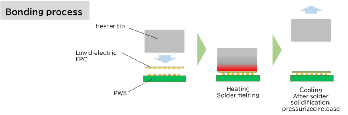
Adopt a pulse heat method
Instead of always keeping the tip hot, apply pressure and drive current briefly to heat the tip, using a pulse heat approach.
Pulse heat enables digital control of heating time and temperature in millisecond units, delivering consistent results regardless of operator skill.
3. Solder volume management
If solder is not supplied uniformly to board terminals, variation in solder will affect impedance.
To suppress variation, pre-solder is applied to the board side to control solder volume.
Combining the measures above and introducing automated or semi-automated equipment such as pulse heat units, is the most reliable way to stabilize assembly quality for high-speed DAC cables.
For soldering AWG32 and rigid boards, Nippon Avionics’ Pulse Heat is recommended
Pulse Heat unit from Nippon Avionics has earned long-standing recognition for soldering electronic components and electronic equipment, as well as ACF bonding.
For soldering AWG32 DAC cables, Pulse Heat unit “TCW-DP100B”, capable of controlling temperature and displacement, is well received.
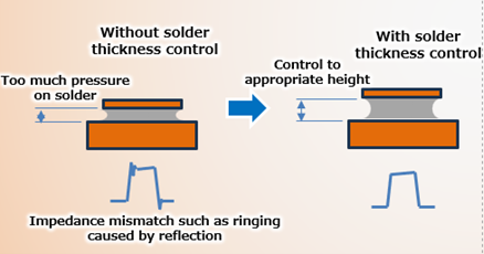
A thermocouple monitors the tip (heater tip) temperature, preventing overheating and insufficient heating.
With displacement control, heating stops when the set solder sink-in amount is reached, pressure stops after cooling, and variation at the soldered area is suppressed.
By suppressing variation, signal reflections and communication errors are reduced, preventing lower speed and poor signal quality.
For detailed specifications, please see the product page for the displacement-control Pulse Heat power supply TCW-DP100B.
How to Solder AWG 32 Wire to a Rigid-flex PCB

| Joining Method | Pulse Heat (Hot Bar Reflow) Soldering |
|---|---|
| Processing Method | Soldering |
| End Products | DAC cables |
Sample Testing
We will be pleased to test your sample with our proposed joining method, and return it with a report.
Related Link
Applications
Products
- Pulse Heat (Hot Bar) Displacement Type TCW-DP100B
- Reflow System Head
- Heater Tip&Heater Tool for Pulse Heat (Hot Bar) Soldering Machine